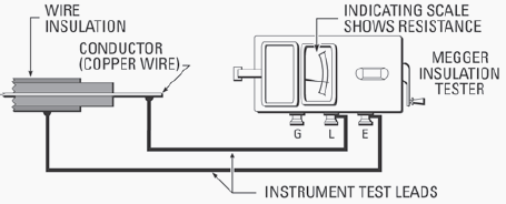
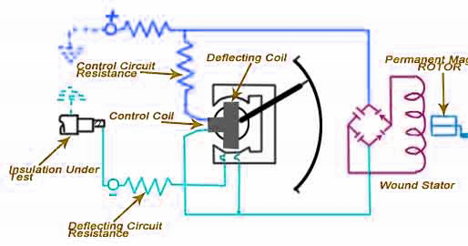
Cable sheath testing resistance test megger cables voltage drum low elandcables Cable sheath resistance testing Megger insulation tester circuit diagram
Megger | Construction & Working | Engineeringa2z
Megger circuit diagram and working pdf Circuit diagram of megger testing Megohmmeter working principle
Megger insulation tester circuit diagram
Megger test procedure for motors pdfWhat is megger? Insulation resistance test or megger test procedures with circuit diagramMegger circuit diagram.
Megger working instruments testingMegger used test do does must considered factors while Electrical topics: megger testing instrumentsInsulation resistance test or megger test procedures with circuit.

What is megger? working, construction, diagram & applications
Megger insulation test resistance electrical ohmmeter circuit instrument principle diagram part working generator method testing typical using digital measure terminalMegger working principle types history uses of megger, 54% off Megger calibration insulation measurement jasa kalibrasi insul principle resistance resistances practically isolasi tahanan listrikCable megger test.
Megger test insulation resistance diagram circuitWhat is megger test? Megger diagram circuit simplifiedElectronic megger circuit diagram.

Electrical and electronics study portal: simplified circuit diagram of
Megger test circuit diagramMegger transformer Megohmmeter megger principlePower cable test with megger:testing diagram & procedure..
Three phase motor test with megger: testing diagram and procedure.Megger – theory, construction & diagram Megger circuit diagramMegger insulation resistance circuit test diagram simple electrical tpub procedures coil figure.

Circuit diagram of megger
Megger construction circuit working coil definition magnetic circuitglobeMegger schematic insulation symbols instrumentationtools principle conductor sheath resistor looked resistances Insulation resistance test or megger test procedures with circuitFigure 17 simple megger circuit diagram.
Megger construction diagram simple circuit test explained operation electrical measuring instrumentsMegger circuit diagram Method statement megger testing for power cables & branch circuitMegger test : working, construction and safety measures.

Megger test
Megger schematic diagrams and principleMegger test circuit diagram What is a megger and how is it usedConstruction and working principle of megger for measurement of high.
.

.jpg)
Insulation Resistance Test Or Megger Test Procedures With Circuit

Megger | Construction & Working | Engineeringa2z

Megger Schematic Diagrams and Principle - InstrumentationTools

Megger Test : Working, Construction and Safety Measures

Circuit Diagram Of Megger Testing - Circuit Diagram

Three phase motor test with Megger: testing diagram and procedure.

What is a megger and how is it used | Instrumentation and Control